CURRENT ELECTRICITY
Introduction
In Chapter One, you learnt the concept of electric charge which was stationary
or static. In this chapter, you will learn the concept of current electricity and
simple electric circuits. Also, you will learn about the relationship between
current, voltage and resistance. The competencies developed will enable
to make simple electric circuits, operate electrical appliances in homes and
efficiently use some commercial and industrial facilities such as refrigerators.
-
Concept of current electricity
-
Simple electric circuits
-
Relationship between current, voltage and resistance
-
Current
-
Voltage
-
Resistance
-
Resistors
Current electricity is the flow of
electric charges along a conductor.
To maintain a steady flow of electric
charges, two things are required. First,
there must be a source of electric
charges that is capable of moving and
a way of causing it to move. Secondly,
there must be a closed conducting path
in which the charges move ultimately
returning to the source. This closed
path is called an electric circuit (see
Figure 2.1). Copper wires are normally
used as conducting pathways for the
electric charges to flow. If focus is put
on one point in the electric circuit for
the purpose of determining the amount
of electric charges passing that point
in a given period of time, then the
electric current has been determined.

The amount of the electric current in a
material depends on the number of charges
taking part and the speed at which they are
moving. In a simple electric circuit, the
charges that flow are the electrons.
Electric current
is the amount of
charge passing a given point in a circuit
in one second. It is a fundamental
quantity.
Mathematically,
Electric current, I = Quantity of charge, Q / Time, t
I = Q / t
But, Q = ne
Where: n = number of charges
e = charge of single electron
Therefore, I = ne / t
Thus, from the formula:
Electric current = Rate of flow of charge
= (the number of charge carriers per second) x (charge of a single electron)
From this definition, the SI unit of an
electric current is coulomb per second
(C/s) where, 1 C/s = 1 ampere (A).
Other units are milliamperes (mA),
kiloamperes (kA) and microamperes, (µA).
Their equivalence to the ampere are as
follows:
1 A = 10³ mA
1 A = 106 μA
1 KA = 1 000 A.
When a steady electric current of 1 A is
flowing in a circuit, a coulomb of charge
passes a given point in the circuit per
second. Coulomb is the SI unit of the
number of charges flowing in a circuit.
A coulomb
is the quantity of electricity
which passes a given point in a circuit
in one second when a steady current
of one ampere is flowing.
Charge movement in an electric circuit
During the 18th century, Benjamin Franklin,
American scientist and statesman,
extensively studied both static and current
electricity. He believed that in an electric
circuit, it was the positive charges (the
protons) that were moving, and his belief
still defines the conventional direction
of the electric current by the direction in
which protons are thought to move.
In most electric circuits the electric current
flows through conductors in which only
negative charges (the electrons) can
move freely. This implies that in most
circuits, electric current is made up of
moving electrons. Just as in a bicycle (see
Figure 2.2), the chain allows energy to be
transferred from the rider to the rear wheel;
the chain does not carry energy. It is the
motion of the chain that allows energy to
be transferred. Likewise, the motion of the
charges carried through a circuit transfers
energy from one point to another. This
means that the actual direction of an electric
current is opposite to the conventional
direction of electron flow.

Sources of electricity
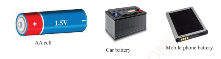
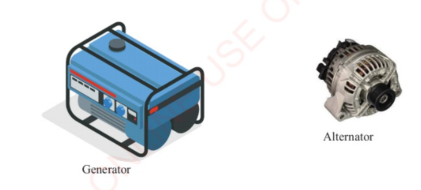
All sources of electric current work by converting some form of energy into electrical
energy. The two basic sources are batteries and generators. Batteries convert chemical
energy into electrical energy while generators and alternators convert mechanical
energy into electrical energy. Figure 2.3 shows some sources of electric current.
Other sources of electric energy include water (hydroelectric power, water currents,
ocean waves), sun, geothermal and wind. These sources are discussed in detail in
chapter nine of this book.
Task 2.1
What are the 10 sources of electricity? How reliable are they? How do they
produce electricity for use? Discuss.

An electric circuit contains a source of moving charge (battery or generator), connecting
wires made of a conducting material (usually copper metal) and various electrical devices
such as bulbs, switches and resistors. The circuit may also contain devices for controlling
the amount of current; these include rheostat, fuses and circuit-breakers, as well as
devices such as ammeters for measuring current and voltmeters for measuring potential
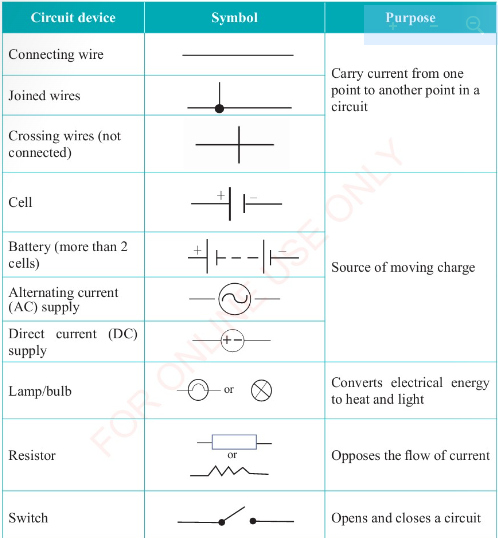
difference. Table 2.1 shows the list of some common circuit components, their purpose
and the symbols used to represent them.
Table 2.1:
Electric circuit components
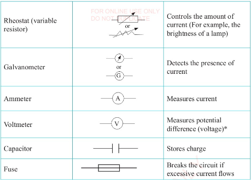
* Potential difference or voltage is the difference in the amount of electrical energy that
charge carriers have between two points in a circuit.
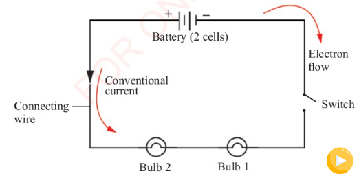
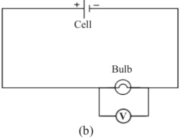
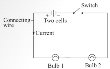
The potential difference between the positive and the negative terminals of a battery
causes a current to flow along any conducting path that links them. Figure 2.4 shows
two bulbs connected to a battery of two cells using copper wires. This combination of
the battery, bulbs, switch and the conducting path formed by the copper wires make up
a simple circuit.
Task 2.2
In groups, list the circuit components that you know. Draw
a chart and indicate the use of each
component and the electric symbol
used to represent it. The best
chart will be hung in the Physics
laboratory.
In an electrical circuit, there is a close relationship between current, voltage and resistance.
An electric current is the rate of flow of
charge through the material. In metals such
as aluminium, gold, silver and copper,
the charge is carried by free electrons. In
solutions, such as sodium chloride, charge is
carried by charged particles known as ions.
Insulators like wood, plastic and rubber
do not have free electrons since every
electron is firmly bound in their atoms or
molecules.
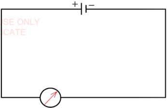
Detection and measurement of electric current
Since the electric current cannot be seen,
it can however be detected by observing
some of its visible effects. Such effects
include the deflection of a galvanometer
when connected to a circuit as shown
in Figure 2.5. Galvanometers can detect
very small currents of a few hundred
microamperes.
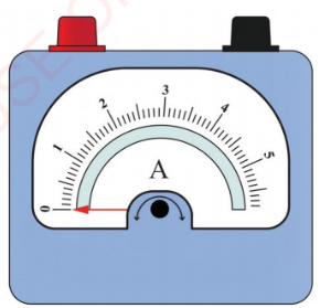
The rate of flow of electrons in a material is
called electric current, and it is measured
in amperes (A) using an ammeter shown
in Figure 2.6. An ammeter is a calibrated
galvanometer constructed with a known
low resistance connected in parallel with
galvanometer circuit. The pointer on the
ammeter indicates the amount of current
passing through it.
The ammeter is connected to a circuit
in such a way that all the current flows
through it. It is designed in such a way
that its presence has little effect on the
current. In essence, the ammeter acts like
another connecting wire.
Ammeters are sensitive to the direction
of the current implying that a wrong
connection can damage them. Therefore,
when connecting to a circuit, the red
terminal (+) should be connected to the
side of the circuit which leads to the
positive terminal of the battery. The black
terminal (-) should be connected to
the side of the circuit which leads to the
negative terminal of the battery.
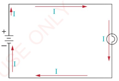
With reference to Figure 2.4, the
current in a simple circuit is the same
at all points, or else the electrons could
accumulate somewhere within the circuit
or even leak away. The electrons leave the
negative terminal of the battery towards
the positive terminal via the connecting
wires as in Figure 2.4. These electrons do
so at the same rate as they flow into the
positive terminal.
Note that, it is not necessary to change
the direction of conventional current
since the flow of electrons is effectively
equivalent to a transfer of positive charge
from the positive terminal to the negative
terminal of the battery. In other words,
the flow of negative charge to the right
is algebraically equivalent to the flow of
positive charge to the left.
Once the circuit is complete, electric
charges inside cells start to flow out into
the circuit. The cells provide the driving
energy for the electrons. The electrons in
turn lose all potential energy as they flow
round to the other terminal. Energy lost
to the bulbs is normally given out as light
and heat.
The amount of electric current required
to run various electric appliances varies
depending on the intended use. For
example, a car headlamp requires a
current of about 4 A passing through it
while a small torch uses about 0.2 A.
Activity 2.1
Aim:
To measure current in a
simple circuit.
Materials:
Connecting wires,
ammeter, battery, bulb and a switch.
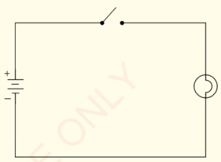
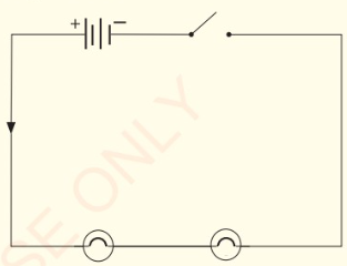
Procedure
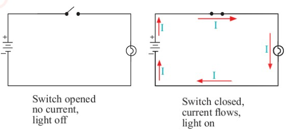
1. Using a battery, a bulb, a switch and
connecting wires, construct a circuit
that allows you to turn the bulb
and off as shown in Figure 2.7.
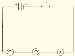
2. Connect an ammeter in the circuit
as shown in Figure 2.8
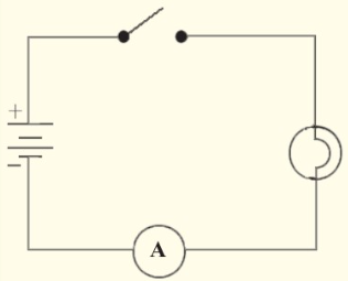
3. With the switch open, measure and
record the current in amperes.
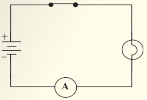
4. Close the switch, then measure
and record the current as shown in
Figure 2.9.
Do Activity 2.1
Question
Explain your observations and
measurements.
In measuring electric current in the
circuit, the ammeter must be connected
in series with the battery and the bulb.
This arrangement enables the ammeter to
experience the same amount of current in
the circuit as the bulb. When the switch
is opened, no current flows, light goes
off and no reading is observed on the
ammeter. When the switch is closed,
current flows, light goes on and the
ammeter reading is observed.
Example 2.1
An electric current of 0.12 A passes a
certain point along a conducting wire.
How much electric charge is flowing
past this point in a minute?
Solution
Current = 0.12 A
Time = 1 min = 60 s
Required: Electric charge
Charge = current x time
Q = I x t
0.12 A x 60 s
= 7.2 C
Therefore, the electric charge flowing past the point is 7.2 C
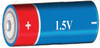
Every cell has a voltage, commonly
referred to as potential difference across
its terminals. It is this potential difference
(p.d) that causes the flow of electrons
(charges) in a circuit. For example, a dry
cell shown in Figure 2.10 has a voltage of
1.5 V. This voltage is normally marked on
the cell.
The larger the voltage, the higher the flow of
electric current through a conducting medium
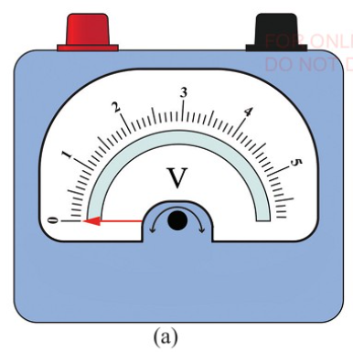
and vice versa. Thus, voltage is defined as the
difference in electric potential between two
points. Voltage is measured using a voltmeter,
as shown in Figure 2.11 (a). The SI unit for
voltage is the volt (V).
A volt
is the energy given to each
coulomb of charge.
Voltmeter is connected across a component
in a circuit, so that its positive terminal is
connected towards the positive terminal
of the battery and its negative terminal is
connected towards the negative terminal
of the battery. For such connection, a
voltmeter draws very little current from the
battery, and its overall effect on the current
in the main circuit is almost negligible.
The potential difference (p.d) between the
ends of a connecting wire is zero volts
since there is almost no loss of potential
energy over the section. Note that if 1 joule
of potential energy is changed into other
forms of energy when I coulomb of charge
passes between the points in a circuit, then
the p.d between the two points is 1 volt.
Sum of p.d around a conducting path = p.d across the battery terminals.
As current flows through the circuit,
it encounters some opposition. This
opposition determines the amount of
current flowing in an electric device. All
materials offer some resistance to the
flow of electric current. Insulators offer
high resistance while conductors offer
low resistance. Amount of current flow
depends on the voltage (p.d) across a
material and the nature of the material.
The higher the resistance the lower the
current for a given voltage.
George Ohm observed that voltage across
a conductor was directly proportional
to the electric current flowing through
it provided that temperature and other
physical conditions of the conductor were
kept constant.
Hence, V oc I
V = IR
where R is the constant of proportionality.
This constant is called resistance and the
above relationship is known as Ohm's
law.
Ohm's law
states that at constant
temperature and other physical
factors, a current passing through a
wire (conductor) is proportional to the
potential difference across its ends.
This implies that,
Resistance, R = p.d across the conductor, V / current through the conductor, I
Therefore, a resistance of 1 ohm is obtained when a p.d of 1 V causes a current of 1 A
to flow in a circuit.
Resistance is measured in ohms (Ω). Other multiples of the unit are kiloohm (kΩ) = 10³ Ω,
megaohm (ΜΩ) = 10 Ω, milliohm (mΩ) = 10 3 Ω and microohm (μΩ) = 10 6 Ω.
Resistors are the most commonly used electronic components that play a vital role in
a circuit. These components are designed to offer specific resistance to the flow of an
electric current in a circuit. They can maintain currents and potential differences at the
levels needed for other circuit components to function properly.
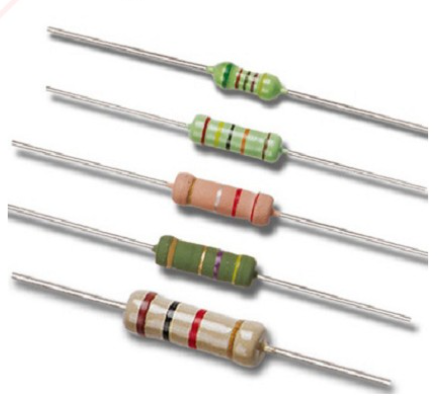
A resistor whose value does not change with the change in voltage is called fixed resistor
or standard resistor. Standard resistor values can be checked from a resistor colour-code
chart. Resistors whose values can be changed by the experimenter are called variable
resistors. The rheostat in Figure 2.12 (a) is an example of the variable resistor. Figure
2.12 (b) shows a fixed resistor with colour codes.
Materials through which current flow
is directly proportional to the p.d
across them, at a steady temperature,
are said to obey Ohm's law. They are
referred to as Ohmic conductors.
A graph of voltage against current
for an ohmic conductor is shown in
Figure 2.13.
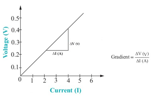
The gradient of the graph represents
resistance. The gradient is constant.
The resistance of a particular wire or
conductor is constant. If the voltage is
doubled, so will the current. The graph
of voltage against current passes through
the origin. The results obtained from
various experiments have shown that the
resistance of a conductor is affected by
several factors. These include;
1. Length of the conductor
A short length of a wire has small
resistance while a long wire of the
same material and thickness has a
large resistance.
2. Temperature
The higher the temperature of the
conductor the higher the resistance
and vice versa. The resistance of
most metal conductors increases with
increase in temperature, though this
is much less in some cases than in
others. In such a case the conductor
does not obey Ohm's law. Hence:
(a) Constantan (copper - nickel
alloy) is used in standard
resistors since its resistance
changes to a very small extent
in a wide range of temperature.
(b) Connecting wires used in circuits have a very low resistance to
keep the energy that is wasted
elements of electric kettles and
as heat to a minimum. Heating
cooker are made from wires of
known large resistance to ensure
that heat (thermal energy) is
released at a specific rate.
3. Nature of material
The conducting ability of a material
has to be considered. A nichrome wire
has higher resistance than a copper
wire of the same dimension. This
is why nichrome wires are used in
heating elements of electric heaters.
Also, due to its low resistance,
copper is mostly used for connecting
wires in circuits, including wiring in
houses.
4. Cross-sectional area
A thin wire has higher resistance
than a thick wire of the same length
and material. The filament of a bulb
is made up of a very thin tungsten
wire. It therefore has a high resistance
necessary to produce large amount of
heat to light the bulb.
Comparing copper and nichrome wires,
these factors can be summarised as shown
in Figure 2.14.
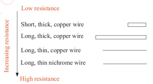
With all other factors being kept constant,
a long wire has a higher resistance than
a short wire, and a thin wire has a higher
resistance than a thick one.
Construction of simple electric circuits
Figure 2.15 shows a circuit consisting of
a battery, a switch and 2 bulbs.
When the switch is closed, the current
flows through the circuit, and the
bulbs light up. The circuit is said to be
complete. When the switch is opened, no
current flows through the wire as the path
carrying the current is broken. The circuit
is said to be incomplete.
When constructing an electric circuit, we
must be certain that there is a complete
path for the current to flow from the battery
through any external devices and back to
the battery. It is a good idea
to first sketch a schematic
diagram of the circuit. On
the diagram, use a pencil to
trace the path the current will
follow. You should be able
to do this without lifting the
pencil. Also, remember that
the conventional current is
the flow of positive charge,
Physics for Secondary Schools
so the current leaves the positive terminal
of the battery and returns to the negative
terminal.
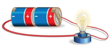
Consider a simple circuit containing two
dry cells, a lamp and connecting wires
as shown in Figure 2.16 (a). Figure 2.16
(b) is the schematic diagram showing the
direction of the conventional current of
this circuit.
A switch can be added to the circuit so
that the light can be turned on and off as
shown in Figure 2.16 (c).
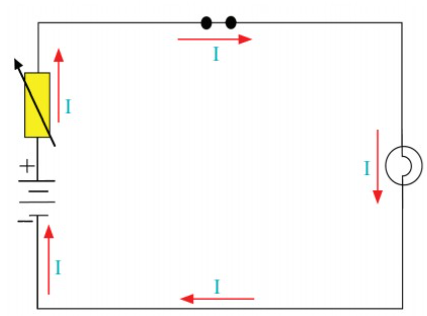
In order to control the brightness of the
lamp, a rheostat has to be included in the
circuit as shown in Figure 2.16 (d).
To determine the amount of current
flowing in the circuit, an ammeter is
inserted as shown in Figure 2.16 (e).
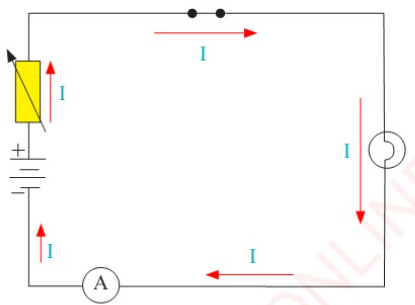
In a circuit, an ammeter is always
connected in series to the battery. The
current has to pass through the ammeter if
it is to be measured. Unlike the ammeter,
a voltmeter is connected in parallel to a
component so as to measure the voltage
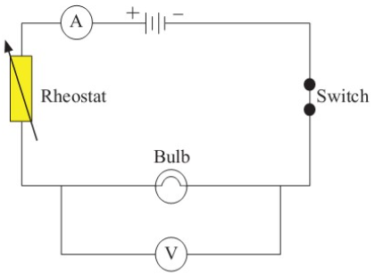
drop across it. Figure 2.17 shows a simple
electric circuit in which the ammeter and
voltmeter are connected in series and
parallel to a bulb, respectively.
As already learnt, resistance is the ratio of
the potential difference across the ends of
a conductor to the current flowing through
the conductor. Radio and television sets
contain large number of resistors, ranging
from few ohms to millions of ohms.
Some are made by winding wire while
others are made from carbon or graphite.
For connection purposes, resistors are
provided with wire ends or terminals as
shown in Figure 2.18.
Activity 2.2
Aim:
To verify Ohm's law.
Materials:
Voltmeter, ammeter,
connecting wires,
cell, variable resistor,
unknown resistor, switch
Procedure
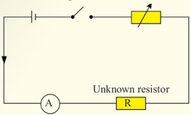
1. Connect a switch, an ammeter,
unknown resistor and the variable
resistor to the battery in series as
shown in Figure 2.19.
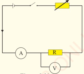
2. Connect a voltmeter parallel to
the unknown resistor as shown in
Figure 2.20.
3. Close the switch, then record the
ammeter and voltmeter readings.
4. Adjust the rheostat so that the lowest
possible current and corresponding
voltage are obtained.
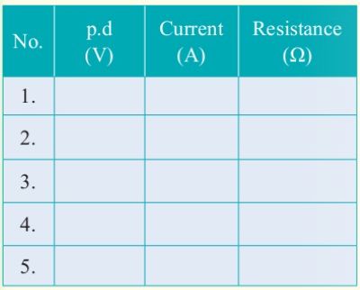
5. Move the sliding terminal of the
rheostat to increase the current
gradually. Record the values of
current, I and potential difference,
V in Table 2.2.
Do Activity 2.2
Question
Calculate the resistance of the
unknown resistor.
The resistance of the unknown resistor, R is calculated using the formula: R = V / I The
average of the values in the third column of
Table 2.2 gives a value for the resistance
of the unknown resistor. In the above
activity, the rheostat (variable resistor)
has been used for varying the current in a
circuit. Note that, as the sliding terminal
of rheostat moves, it varies the length of
the conductor being used in making the
rheostat.
Note:
For a single loop or simple circuit:
1. Current is the same at all points
around the circuit.
2. The sum of the potential differences
around a conducting path from one
battery terminal to the other terminal
within the circuit is the same as the
p.d across the battery.
Example 2.2
A resistance wire of 20 2 is connected across a battery of 5 V. Calculate the
current in the circuit.
Solution
Resistance, R = 20 Ω
Potential difference, p.d = 5 V
Required: Current, I= ?
From; I= V / R
= 5V / 20 Ω
= 0.25 A
Therefore, the amount of current is 0.25 A.
Example 2.3
An ohmic conductor has a voltage drop of 9 V measured across it. The current
flowing in the conductor is 3 mA. What is its resistance?
Solution
Voltage drop, V = 9V
Current, I = 3 mA =3 x10-³ A
Required: Resistance, R = ?
From; V=IR
R = V / I
= 9 V / 3 × 10-³ A
= 3000 Ω
Therefore, the resistance is 3 000 Ω.
Example 2.4
Calculate the readings of the voltmeter P and the ammeter Q in the electric circuit in
Figure 2.21 when the switch is closed.
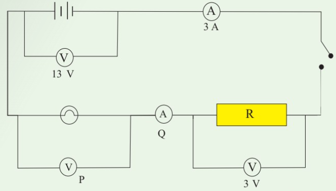
Solution
Being a single loop circuit, the current is the same at all points.
Therefore, the reading of ammeter Q is 3 A.
Sum of p.d in external circuit = p.d across battery
3V + P = 13 V
P = 10V
Therefore, the reading of Voltmeter P is 10 V.
Exercise 2.1
1. In an experiment to determine the value of resistance, the following results were
obtained.
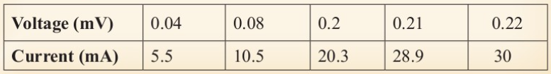
From the experimental results:
(a) draw a graph of Vagainst I
(b) determine the resistance R
2. A current of 0.25 A flows through a circuit of voltage 10 V across a bulb. What
is the resistance of the bulb?
3. Describe factors that affect the resistance of a conductor.
4. (a) What do you understand by an ohmic conductor?
(b) A resistor has a resistance of 500 2. How could this resistance be measured
experimentally?
(c) Which has a greater resistance; a long, thin, hot nichrome wire or a short,
thick, cool copper wire?
(d) If a p.d of 6.0 V is measured across the ends of a wire of resistance 12 2,
(i) determine the current that flows through it.
(ii) calculate the p.d that is required to produce a current of 1.5 A flowing
through it.
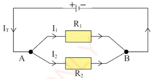
Task 2.3
In groups, collect wires of
different thicknesses (cross-
sectional areas) and carry out
the following tasks inside the
Physics laboratory.
1. Measure and record the
lengths and thicknesses of
the wires.
2. Use Figure 2.22 to construct
a simple circuit that can
compare the current passing
through each of the wires
connected between A and B.
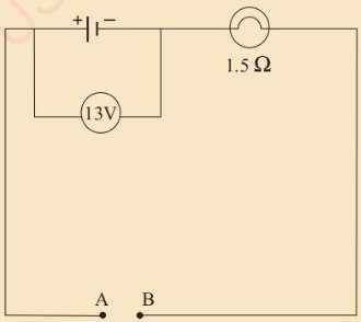
3. List the wires in their order of
increasing resistance.
Connection of resistors
Resistors can be connected either in
series or in parallel depending on the
desired output.
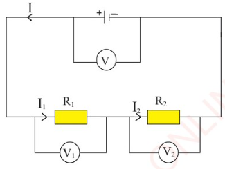
(a) Series connection
In series connection, the resistors are
connected end to end as shown in
Figure 2.23. In this case, voltages are
additive. The total potential difference
(V
T
) is given by;
V
T
= V₁ + V₂
This means that the sum of the p.d across
the resistors is the same as the p.d across
the battery. The current is the same at all
points around the circuit. That is;
I₁ = I₂ = I
From Ohms' law,
V = IR
Then,
V₁ = I₁R₁ and V₂ = 1₂R₂
V
T
= I₁R₁+I₂R₂ = IR
T
Since the current flowing through the
resistors is the same;
IR
T
= IR₁ + IR₂
R
T
= R₁ + R₂
Therefore, total resistance or equivalent
resistance for resistors in series is equal
to the sum of individual resistances.
(b) Parallel connection
Resistors are connected across two
common points in a parallel arrangement
as shown in Figure 2.24.
In parallel connection, potential difference
is from a single source; so, it is the same
for all the branches. However, the current
is different in each branch.
From Figure 2.24:
Total current I
T
= 1₁ + 1₂
From Ohm's law;
V = IR
I = V / R
Then, I
T
= I₁ + I₂
v / R
T
= V / R₁ + V / R₂
V(I / R
T
) = V(I / R₁ + I / R₂)
I / R
T
= I / R₁ + I / R₂
R
T
= R₁R₂ / R₁ + R₂
Therefore, total resistance
for two resistors connected in parallel is given by;
Total resistance = Product of resistances / Sum of resistances
When resistors are connected in series,
they give larger resistance than when
connected in parallel. In parallel
connection, each resistor has the same
potential drop across it, and the currents
through each resistor may be different
depending on the resistance of a given
resistor.
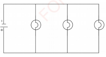
Note that, where bulbs have to be powered
by a single source of electric current,
the bulbs are connected in parallel (see
Figure 2.25). This is practised in cars and
home lighting systems. The advantages
of a parallel connection over a series
connection are:
1. The full p.d of source is applied
across each bulb irrespective of
the number of bulbs.
2. Switching one bulb on or off does
not affect the others.
Activity 2.3
Aim:
To study the flow
current through bulbs
connected in series and
parallel.
Materials:
Bulbs, bulb holders,
ammeters, battery of
2 cells, switch, connecting
wires
Procedure
1. Connect a battery to two bulbs
arranged in series as shown in
Figure 2.26.
2. Add a suitable ammeter by
connecting it to the circuit as shown
in Figure 2.27.
3. Switch on the circuit and note the
ammeter reading.
4. Record your observations.
5. Open the switch, then move the
ammeter to different positions
within the circuit as shown in
Figure 2.28.
6. Switch on the circuit and record
your observations.
7. Remove one bulb from the series
circuit and record the ammeter
reading.
8. Now, connect the two bulbs in
parallel as shown in Figure 2.29.
9. Add switches by connecting
them to your circuit as shown in
Figure 2.30.
10. Switch on the circuit and record
your observation.
11. Connect three ammeters to the circuit
as shown in Figure 2.31, close the
switches and record the readings.
Do Activity 2.3
Questions
(a) What can you conclude about
the current in steps 3, 6 and 11?
(b) How are the light bulbs in
your home connected?
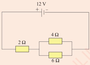
Example 2.4
Consider the circuit shown in Figure
2.32. If the p.d across the battery is 24 V,
calculate the p.d across the 4Ω and 6Ω
resistors.
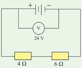
Solution
Total resistance in the
circuit = 4 Ω + 6 Ω = 10 Ω
Using Ohm's law, I = V / R
Current in the circuit,
= 24 V / 10 Ω
= 2.4 A
Voltage across 6 Ω and 4 Ω
p.d across 6 Ω
V = IR
= 2.4 x 6
= 14.4 V
p.d across 4 Ω
V = IR
= 2.4 x 4
= 9.6 V
Therefore, p.d across 6 Ω and 4 Ω are
14.4 V and 9.6 V, respectively.
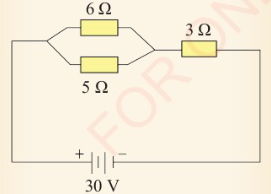
Exercise 2.2
1. Use information in Figure 2.33 to
calculate:
(a) the p.d across the 5 Ω resistor.
(b) the current value across the
resistor of 3 Ω.
2. What is the difference between
series and parallel circuit
connection?
3. What is the p.d across the 2
resistor in Figure 2.34?

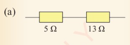
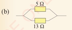
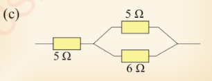
4. Calculate the combined resistance
in Figure 2.35 (a), (b) and (c).
Chapter summary
1. Electric current is the amount of
charge passing through a given
point in a circuit per second.
2. Electric current is expressed
as the rate of flow of electric charge, I = Q / t.
3. Electric current is one of the
fundamental quantities and is
measured in units of coulombs (C)
per seconds (s) called amperes (A).
4. The direction of conventional
current is opposite to the flow of
electrons.
5. Electric current flows in all
complete paths that allow it to
return to its source. Electric
circuits contain a source of
moving electric charges such as a
battery or a generator.
6. Resistors are used to control the
flow of current and voltage in a
circuit while obeying Ohm's law.
7. Ohm's law states that "at a
constant temperature and other
physical factors, voltage across
the ends of a conductor is directly
proportional to the current
flowing through that conductor".
8. Resistance is the ratio of the
potential difference across the
ends of a conductor to the current
flowing through that conductor.
9. The voltage is the amount of
potential difference in an electric
circuit.
10. Ammeters are connected in series
to the source of electric charge
while voltmeters are connected in
parallel to the load and battery.
11. Total resistance for resistors
in series is equal to the sum of
individual resistances.
12. For any two resistors connected
in parallel;
Total resistance = Product of resistances / Sum of resistances
That is;
R
T
= R₁R₂ / R₂ + R₁
13. The amount of current in a circuit
can be measured by using an
ammeter.
Revision exercise 2
Choose the most correct answer in
items 1-3.
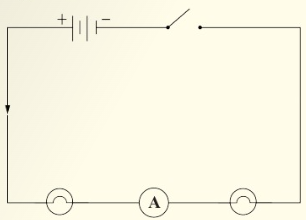
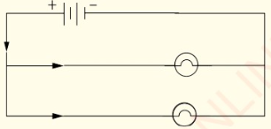
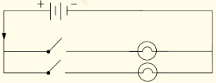
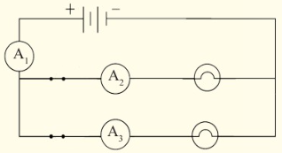
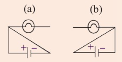
1. For a device in an electric circuit
to work, the current must flow
through it. Using Figure 2.36,
select the circuit in which
will light.
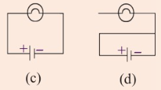
2. A current of 1.0 A passes in the circuit shown in Figure 2.37. What is the
resistance of P?
3. The resistance of most metal conductors:
(a) increases with increasing temperature.
(b) increases with decreasing temperature.
(c) decreases with increasing temperature.
(d) decreases with decreasing temperature.
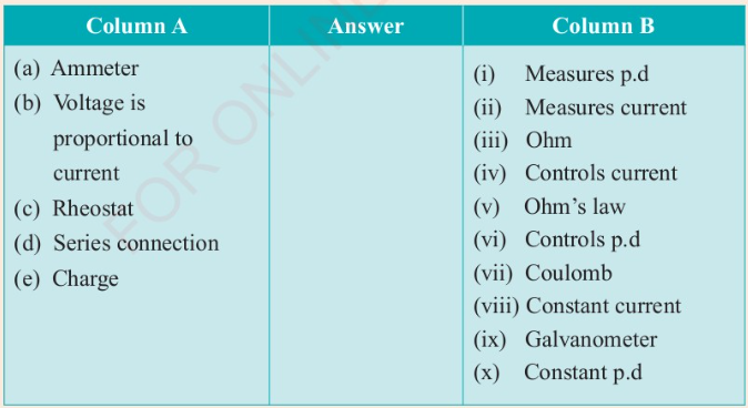
4. Match each item in column A against its corresponding item from column B
by writing the correct response in the answer column provided.
5. (a) Explain the following
concepts:
(i) electric current.
(ii) resistance.
(iii) voltage.
(b) Convert these currents into
amperes:
(i) 500 µA.
(ii) 250 μA.
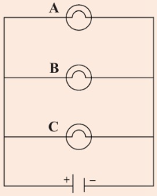
6. In an electric circuit, the current
will flow along any complete
path that allows the current to
return to its source. In the circuit
shown in Figure 2.38:
(a) Which bulb will light? why?
(b) Sketch the circuit in (a)
and use arrows to show
the direction in which the
current flows.
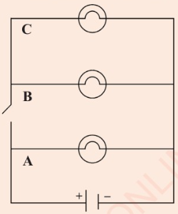
7. Consider the circuit in Figure 2.39;
(a) If bulb A burnt out, will bulbs
B and C light up? Explain
your answer.
(b) Sketch the circuit in (a) and use
arrows to show how the current
will flow after bulb A burns out.
8. (a) Differentiate between potential
difference and current.
(b) Using a diagram, show how
an ammeter is connected
to measure the current flowing
through resistor, R.
(c) Draw a circuit diagram
to show how a voltmeter is
used to measure the potential
difference of load, R.
9. (a) State Ohm's law.
(b) What is the SI unit of resistance ?
10. What could be the effect on the
resistance of a conductor if:
(a) its length was increased?
(b) its temperature was increased?
(c) its cross-sectional area was
reduced?
11. A current of 100 mA flows
through a 5 k2 resistor. Determine
the p.d across the resistor.
12. Three resistors of 2 2, 3 2 and
6 are connected in series to a
3 V battery. What is the current in
the circuit?
13. (a) Two resistors of 6 2 and 12
are connected in parallel.
Calculate their total resistance.
(b) Two resistors of 3 2 and 6
are connected in parallel.
(i) Draw the schematic
diagram of the circuit.
(ii) Determine the total
resistance of the circuit.
(iii) Calculate the p.d of the
circuit when the current
across it is 5 A.
14. Consider the circuit in Figure 2.40.
(a) Find the equivalent resistance.
(b) Determine the current in the
circuit.
15. Suppose an additional 2 2 resistor
is connected in parallel to the cell
in Question 14.
(a) Draw the circuit diagram.
(b) Calculate the resistance of the
circuit.
16. Basing on your observations in
Activity 2.1, does adding an
ammeter to a circuit affect the
amount of current flowing?
Explain your answer.
17. Two resistors of resistances 2 Q
and 4 2 are connected to a
Calculate the resistance of the
circuit when:
(a) resistors are connected in
parallel.
(b) resistors are connected in
series.
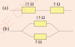
18. Considering Figure 2.41, which
one has a lower combined
resistance?
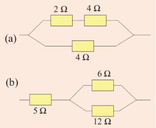
19. Calculate the combined resistance
for each in Figure 2.42 (a) and (b).
20. Given two resistors, 4 and 6 2, and a battery, explain how you can connect
them in a circuit.
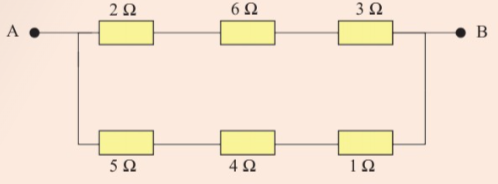
21. If the p.d between points A and B in Figure 2.43 is 22 V, calculate the current
between the points.