MEASUREMENT
Introduction
Measurement is a word used in everyday life. We measure a piece
of land in hectares or acres, and the circumference of a
playground using a tape measure. In physics, accurate and
precise measurements enable the collection of useful
experimental data that can be tested against theoretical
predictions to enhance the development of physical theories. In
this chapter, you will learn about the concept of measurement of
physical quantities, the basic apparatus/equipment used in
measurement and how to use them. The competencies developed will
enable you to deal with different situations involving
measurements.
-
Concept of measurement
-
Physical quantity
-
Basic equipment / apparatus and their uses
-
Derived quantities
-
Sources of errors
The word 'measurement' comes from the Greek word 'metron' which
means 'limited proportion'. It is our common experience that, if
you want to buy a trouser, the information that a shopkeeper first
wants to know is the size of the trouser that fits your waist. If
it happens that you do not know your size, he or she will take a
tape and measure the size of your waist. The act of finding the
size of a given quantity is referred to as measurement.
Measurement is defined as the process of assigning a number and a
unit to an observation or event. Measurement is done through
comparing the known and unknown quantity. For example, in
measuring the length of a table, we have to compare a table with a
ruler or a tape measure.
Every measurement has two parts which are:
1. a number or numerical part that gives the result of the
comparison; and
2. A unit part which identifies the particular unit used to make
the measurement.
In the unit part, the focus is on the standard unit (International
System Units-SI units) though, other units may also be used. For
example, if the length of a playground is 100 m, '100' is the
number part while 'm' is the unit part. Therefore, a meaningful
measurement must have both a number and a unit.
A complete measurement which includes both number and unit part is
called measurement of a physical quantity. For example, the
measurement of 100 km, 2 kg or 10 s.
A physical quantity is any measurable quantity. Physical
quantities are divided into two categories, namely fundamental
physical quantities and derived physical quantities.
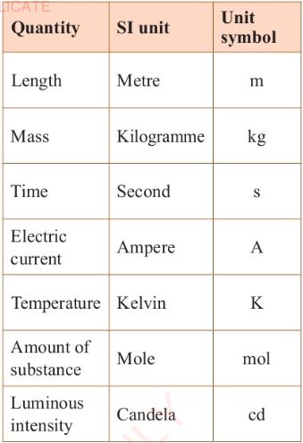
Fundamental physical quantities
Fundamental physical quantities are quantities of measurement
which cannot be expressed in terms of other quantities. These
include; length, mass, time, temperature, amount of substance,
electric current and luminous intensity. Among the measured
fundamental physical quantities mass, length and time are the
most common. Table 3.1 shows the fundamental physical quantities
and their respective SI units of measurement.
Table 3.1:
The fundamental physical quantities and their SI units.
Vector and scalar quantities
The pysical quantities can futher be classified into either
vector or scalar. quantities.
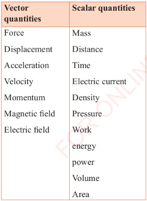
Vector quantities
Vector quantities are those quantities that have both magnitude
and direction. Examples of vector quantities are force,
displacement, velocity and momentum.
Scalar quantities
Scalar quantities are those quanties that have magnitude but
have no direction. Examples of scalar quantities are mass,
distance, time, density, volume, pressure, speed, electric
current, work, energy, and power.
For example, consider a car travelling at 100 kilometres per
hour North. This describes the velocity of the car which is 100
kilometres per hour in the North direction. Velocity is a vector
quantity. However, if the intention is to describe only the
speed of the car and not the direction, the statement could be
simply that the car is travelling at 100 kilometres per hour.
Speed is a scalar quantity.
Table 3.2 gives some of the vector and scalar quantities.
Table 3.2:
Some of the vector and scalar quantities
Measurement of length
Length is the most commonly measured quantity in daily life.
Length is used to give the dimensions of an object or the
distance between two points. Hence, distance is defined as the
path taken by a particle in space between two points or objects.
The distance around the surface of an object is called
perimeter. You can measure the distance ranging from very small
to a very large distance such as the distance from the earth to
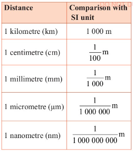
the sun. To cope with this large difference, there are several
other units obtained from the metre, namely, kilometre (km),
centimetre (cm), millimetre (mm), micrometre (um), nanometre
(nm), picometer (pm) and femtometre (fm). Their equivalence is
as follows:
1 km = 1 000 m.
1 m = 100 cm.
1 cm = 10 mm.
1 mm = 1 000 µm.
1 μm = 1 000 nm.
1 nm = 1 000 pm.
1 pm = 1 000 fm.
Table 3.3 gives some of the units in comparison to the metre.
Very small lengths are measured and expressed in mm, um, nm, pm
or fm.
The length of an object is measured using specific instruments.
The choice of an instrument to be used is determined by the
following factors.
1. The desired degree of precision.
2. The size of the physical quantity to be measured.
3. The shape of the object.
Table 3.3:
Gives some of the units in comparison to the metre.
Before you perform an experiment, you should be comfortable with
equipment or apparatus that you will use. The following section
describes some of the common ones and how to use them.
Equipment that are commonly used in a laboratory to measure
length are a metre rule, tape measure, vernier caliper and
micrometer screw gauge.
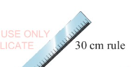
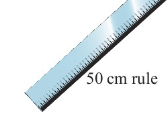
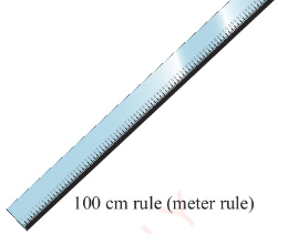
Metre rule
In an elementary physics laboratory, the metre rule, half-metre
rule, and 30 cm rule as shown in Figure 3.1, are recommended to
be used. These rulers are mainly wooden or plastic and are
graduated in centimetres and millimetres. A typical metre rule
has markings for 1 cm and 1mm intervals
Task 3.1
1. If you have to measure the length of a field, which type of
instrument will you use?
2. Place the following objects on the paper. Mark the end points
of each. Draw the line-segment for the length of each object and
find the measure of length.
(a) A pencil
(b) A book
(c) A match stick
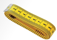
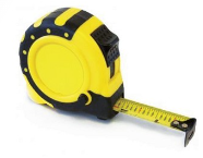
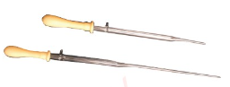
Tape measure
A tap measure, as shown in Figure 3.2, is a flexible ruler used
to measure long Student's Book Form One distances and lengths of
objects which are not straight. It is commonly used in civil
work, for example in construction sites for houses, roads and
bridges. It has the accuracy similar to the metre rule, with the
minimum distance to be measured as 1 mm. Two basic types of tape
measures are shown in Figure 3.2.
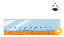
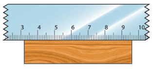
When taking a measurement, always ensure that your eye is
perpendicular to the mark on the scale of the metre rule, as
demonstrated in Figure 3.3, otherwise the value will have an
error. An error caused by wrong positioning of the eye is known
as parallax error. Such an error occurs when the measurement of
an object's length is more or less than the true length, because
of the eye being positioned at an angle to the measurement mark.
Therefore, the eye should be perpendicular to the point you are
reading, as shown in Figure 3.3.
Care should be taken while using a metre rule so as to avoid
damaging the ends. This is because the rule does not have an
allowance (a short ungraduated portion) for wear at both ends.
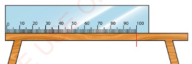
Suppose, you wish to measure the length of a table. The zero (0
cm) mark of the metre rule is aligned with one end of the table,
as shown in Figure 3.4.
Since the metre rule does not extend beyond the end of the
table, we carefully mark the point on the table that corresponds
to the end of the metre and then continue, as shown in Figure
3.5.
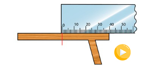
The actual length of the table is then given as: 100 cm + 40 cm
140 cm. Therefore, the table has a length of 140 cm or 1.4 m. In
case the edge of a ruler is worn out, which is almost
inevitable, it is advised to:
(i) always start measuring from the mark more than zero; and
(ii) subtract the mark from the final reading.
Figure 3.6 illustrates the use of a ruler with worn-out edges.
The length of the object = (9.6-3.2) cm = 6.4 cm.
Task 3.2
The following task should be carried out in groups of three
students. Use a metre rule to measure the length and width of
the cover of your physics textbook to the nearest tenth of a
centimetre. Record your results. Calculate the perimeter of the
cover. Perimeter = 2 times the length + 2 times the width = 2
(1+w). Present your results in the class.
A vernier caliper
A vernier caliper is an instrument used to measure small lengths
with a greater degree of accuracy than a metre rule.
Measurement by use of a vernier caliper is obtained to the
nearest hundredth of a centimetre, which means to the accuracy
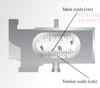
of 0.01 cm. A vernier caliper has a fixed scale and a vernier
scale. The fixed scale is also known as the main scale. The
vernier scale slides along the fixed scale hence readings are
taken from both scales. The fixed scale gives readings in
centimetres and millimetres while the vernier scale gives
readings in the hundredth of a centimetre.
This explains the second decimal place. Figures 3.7 and 3.8 show
a vernier caliper and a vernier scale for taking measurement.
The vernier scale is a short scale. 10 vernier divisions cover 9
main scale divisions.
This is a length of 0.9 cm. When this is divided into 10 equal
intervals, the result is the difference between the main scale
division and the vernier scale division.
This is known as Least Count.
Main scale division = 1 cm / 10 = 0.1 cm.
Vernier scale division = 9 cm / 0.1 = 0.09 cm.
Therefore,
least count of a vernier caliper
= (0.1 -0.09) cm = 0.01 cm.
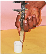
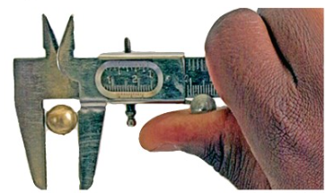
The vernier caliper has a set of 'jaws' that can be used to
measure the lengths of some objects or the thickness of other
objects.
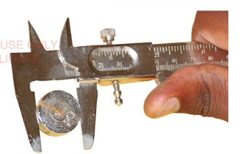
They can also be used to measure the external diameters of
objects using outside (outer) jaws, as shown in Figure 3.9.
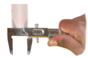
At the top of a vernier caliper are two inner (upper) jaws that
can be used to measure the internal diameter of a hollow
objects, as shown in Figure 3.10. A stem sticks out from the
right side of the caliper is called a depth gauge or a depth
probe. It can be adjusted to measure a depth of an object, as
shown in Figure 3.11.
The screw clamp visible on top of the caliper is tightened to
secure the objects being measured, so that the reading does not
change while measuring.
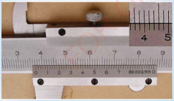
How to read a vernier caliper
The following steps are taken when measuring length using a
vernier caliper.
1. Close the jaws of the vernier caliper and look out for the
zero cm (0 cm) mark differences.
2. Place the object to be measured between the jaws.
3. Slide the vernier along the main scale until it just touches
the end of the object. Use the screw clamp to secure the object
in position, as shown in Figure 3.12.
4. Read and record the reading on the main scale which is to the
left of the zero cm mark of the vernier scale. This value is to
the nearest tenth of a centimetre.
5. Observe along the vernier scale and record the mark which
coincides with a mark on the main scale.
6. Read and note down the value on the vernier scale. This gives
the digit in the hundredth place of the measurement.
7. Add the values in steps 4 and 6 to get your correct reading.
Therefore, length of object = main scale reading + vernier scale
reading.
Example 3.1
Using Figure 3.13, determine the diameter of the object that is
placed between the jaws of the vernier caliper.
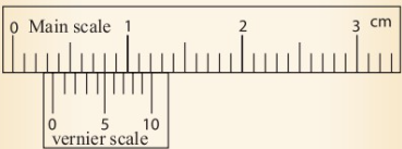
Solution
From Figure 3.13,
Main scale reading = 0.3 cm = 3.0 mm
Vernier scale reading = 5 divisions x 0.1 mm = 0.5 mm
Total reading = Main scale reading + Vernier scale reading
= 3.0 mm + 0.5 mm = 3.5 mm
Therefore, the total reading = 3.5 mm
The diameter of the object = 0.35 cm.
Example 3.2
The jaws of a vernier calliper touch the inner wall of
calorimeter without pressure. The position of zero of vernier
scale on the main scale reads 3.4 cm. The 6th of vernier scale
division coincides with the main scale division. Vernier
constant of callipers is 0.01 cm. Find actual internal diameter
of calorimeter, when it is observed that the vernier scale has a
zero error of - 0.03 cm.
Solution
Main scale reading = 3.4 cm
Least count (L.C) = 0.01 cm
Vernier coincidence = 6
Reading = Main scale reading + Vernier
coincidence x LC
= 3.4 + 6 × 0.01
= 3.4 +0.06
= 3.46 cm.
Corrected reading
= reading - zero error
= 3.46 - (-0.03)
= 3.54 +0.03
= 3.49 cm.
Exercise 3.1
Answer all questions
1. Draw both the main and vernier scales of a vernier caliper to
show a reading of 0.36 cm.
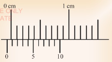
2. What is the reading in Figure 3.14 (a) and 3.14 (b)?

3. The thin metallic strip of vernier caliper moves downward
from top to bottom in such a way that it just touches the
surface of a beaker. Main scale reading of calliper is 6.4 cm
whereas its vernier constant is 0.1 mm. The 4th vernier scale
division coincides with main scale division.
Calculate the actual depth of beaker. (Assume zero end error).
Activity 3.1
Aim:
To measure the external diameter of a test tube using a vernier
caliper.
Materials:
Test tube, vernier caliper
Procedure:
1. Close the jaws of the vernier caliper and observe the zero cm
marks of the main and vernier scales. Record your observations.
2. Open the jaws and place the test tube between them.
3. Close the jaws gently until the test tube is held firmly.
Record your observations.
4. Repeat steps 1 to 3 using other parts along the test tube.
5. Obtain three readings. Record your observations.
Do Activity 3.1
Questions
(a) Calculate the average of the readings obtained.
(b) Were the four obtained readings equal?
(c) Explain why three readings were taken and not one.
A test tube is cylindrical in shape. This means that its
diameter is the same throughout. The readings obtained using the
outside caliper jaws are equal in magnitude since the test tube
is almost uniform in shape.
In an experiment, it is always best to obtain many readings so
as to obtain an average result. Two or more readings offer an
opportunity for the experimenter to compare and identify any
pattern.
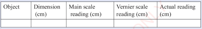
Task 3.3
Collect a variety of objects such as books, pencils and other
writing materials. In your collection, include cylindrical
objects. Use a vernier caliper to measure the thicknesses of the
collected objects. The depth, internal and external diameters of
the hollow objects should also be measured. Record your
measurements in the following table:
A micrometer screw gauge
A micrometer screw gauge gives readings with better precision
than the vernier caliper.
Measurement can be obtained to the nearest thousandth of a
centmetre. This is an accuracy of 0.001 cm. For this reason, it
is usually used to measure the diameters of thin objects like
wires and ball bearings. The micrometer screw gauge has
different parts, as shown in Figure 3.15.
A micrometer screw gauge consists of main scale (sleeve) and
thimble scale. The main scale is marked in millimetres. The
thimble scale is divided depending on the distance between two
consecutive threads of the screw. This is called the pitch of
the screw. If the pitch of the screw of the micrometer is 0.5
mm, then the thimble scale has 50 equal divisions. Otherwise, it
has 100 divisions when the pitch is 1.0 mm.
This means that when the thimble makes a complete turn, the
spindle moves either forward or backward a distance of 0.5 mm or
1.0 mm respectively along the sleeve.
When the spindle is completely closed onto the anvil, the
thimble edge aligns with the zero mark on the sleeve scale. The
thimble also has its zero-mark lying on the central line of the
sleeve scale. Therefore, the gap between the spindle and the
anvil equals the distance between the edge of the thimble and
the zero mark on the main scale.
To measure the diameter, an object is placed between the anvil
and the spindle. The thimble is then rotated using the ratchet
knob until the object is secured firmly between the anvil and
the spindle. This in turn moves the spindle forward. The ratchet
knob must be used to secure the object firmly, otherwise the
instrument will be damaged or give a wrong reading. It is
recommended that three clicks of the ratchet should be obtained
before taking the reading. Note that as the thimble turns, it
slides over the sleeve. The sleeve has a linear scale while the
thimble bears a circular one. Care has to be taken to ensure
that the thimble does not rotate while the reading is being
taken.
Measuring the diameter of a wire by micrometer screw gauge
The following is the procedure for measuring the diameter of a
wire using micrometer screw gauge.
1. Unscrew the thimble to create enough space to accommodate the
wire between the spindle and the anvil.
2. Close the gap by rotating the thimble clockwise. Screw the
ratchet knob until it clicks so as to show the correct setting.
3. Read and note down the value on the sleeve; that is the last
mark must be visible to the left of the thimble. This value is
to the nearest tenth of a millimetre. The value is 7.5 mm as
shown in Figure 3.16.
4. Read and note down the value on the thimble that is just
below the reference line on the sleeve. This value is to the
nearest hundredth of a millimetre (0.28 mm for Figure 3.16).
5. Add the values in steps 3 - 5. Therefore, for Figure 3.16,
Reading = Sleeve Scale Reading (SSR) + Thimble Scale Reading
(TSR) Observed reading = SSR + TSR = 7.00 mm + 0.28 mm = 7.28 mm
Task 3.4
Diameter of a steel ball is measured using a vernier callipers
which has divisions of 0.1cm on its main scale (MS) and 10
divisions of its vernier scale (VS) match 9 divisions on the
main scale. Three such measurements for a ball are given as:
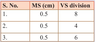
If the zero error is - 0.03 cm, calculate the average corrected
diameter is:
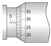
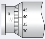
Example 3.4
What is the correct reading for the micrometer screw gauges
shown in Figure 3.17?
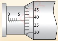
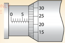
Solution
From Figure 3.17 (a)
(a) Main scale reading = 7.50 mm Thimble scale reading = 0.38 mm
Reading = 7.88 mm.
From Figure 3.17 (b)
(b) Main scale reading = 7.50 mm Thimble scale reading = 0.22 mm
Reading = 7.72 mm.
Example 3.3
When a screw gauge with a least count of 0.01 mm is used to
measure the diameter of a rod, the reading on the sleeve is
found to be 1.6 cm and the reading on the thimble is found to be
48 divisions. What is the correct diameter of the rod, if the
zero error for the gauge is-0 003 cm?
Solution
Least count (LC) of a micrometer screw gauge given = 0.01 mm.
Main scale reading (MSR) = 1.6 cm or 16 mm.
Circular scale reading (CSR) = 48 divisions.
The reading = MSR + CSR x LC
The reading
= 16 mm + 48 x 0.01 mm = 16.48 mm
Correct reading
= 16.48 + 0.03 = 16.51 mm.
Exercise 3.2
Answer all questions
1. What is the reading of the micrometre screw gauge in Figure
3.18?
2. What is the difference between a micrometer having 100
divisions and one with 50 divisions?
3. State one limitation of using a micrometer screw gauge to
measure length.
4. The actual diameter of a lead ball is 3.21 mm. Determine the
reading that would have been obtained if:
(a) a micrometer screw gauge was used.
(b) a vernier caliper was used.
5. When a screw gauge with a least count 0.01 mm is used to
measure the diameter of a wire, the reading on the sleeve is
found to be 0.5 mm and the reading on the thimble is found to be
27 divisions. What is the correct diameter of the wire, if the
zero error for the gauge is - 0 005 cm?
Activity 3.2
Aim:
To measure the diameter of a steel ball using a micrometer screw
gauge.
Materials:
Micrometer screw gauge, steel ball
Procedure
1. Unscrew the thimble anticlockwise to create a gap between the
anvil and the spindle.
2. Hold the steel ball in the gap while rotating the thimble
clockwise until it gently grips the ball.
3. Turn the ratchet knob until it clicks.
4. Record your observations.
5. Unscrew the thimble slightly. Free the ball and turn it
through a certain angle. Then repeat step 3.
6. Record your second observation.
7. Repeat step 5 and note the third observation.
Do Activity 3.2
Questions
(a) Calculate the average of the obtained readings.
(b) Why would you prefer a micrometer screw gauge to a vernier
caliper in measuring this diameter?
A micrometer screw gauge is more accurate than a vernier
caliper. It measures up to three decimal places in the unit of
mm. This means that its degree of precision is to the nearest
thousandth of a centimetre. Unlike a micrometer screw gauge, a
vernier caliper can only measure to a hundredth of a centimetre.
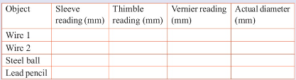
Task 3.5
Collect a variety of pieces of wire of different diameters, lead
pencils and steel balls. In your groups:
1. Find out the smallest division on the main scale of your
micrometer screw gauge and the number of divisions on the
thimble.
2. Measure the diameters of the different objects. Each person
in the group should measure at least one object. Record your
findings in the following table.
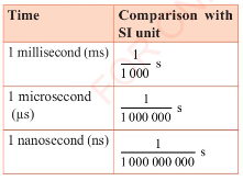
Measurement of time
Time is a measure of the interval between two events, or the
period within which an event takes place. It is the precise
moment as determined by a clock or a watch. The SI unit of time
is second (s). There are smaller units of time that are based on
the second. These are the millisecond (ms), the microsecond
(us), and the nanosecond (ns) as shown in Table 3.4.
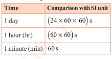
Large units of time are minutes, hours, days, weeks, months and
years as shown in Table 3.5.
Reading time using stopwatch
Time is used to indicate when an event occurs, the order in
which several events occurs or the rate at which an event
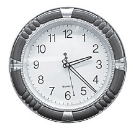
happens. Under normal circumstances, time is usually measured
using a clock or a wristwatch as shown in Figures 3.19(a) and
(b), respectively.

For those experiments that require measurement of time in the
laboratory, stopwatches are used. At this level, we shall
concentrate on measuring time by means of a stopwatch.
A stopwatch is a device that is held in the hand and is used to
show the time elapsed. Thus, the time interval is obtained from
the time it is started to the time it is stopped. It is used
when time must be measured precisely and with a minimum error.
Stopwatches are used for timing laboratory experiments or
sporting events like athletics.
There are two types of stopwatches, namely analogue stopwatch
and digital stopwatch, as shown in Figure 3.20.
An analogue stopwatch has two scales, the minute scale and
second scale. The pointer on each scale enables the time that
has elapsed to be read, see Figure 3.20 (a).
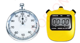
A digital stopwatch shown in Figure 3.20 (b) displays the actual
time in hours, minutes, and seconds. Digital stopwatches are
more accurate than analogue stopwatches. A large digital version
of a stopwatch is called a stop clock. Stop clocks are designed
for viewing at a distance, such as in sports stadia.
How to operate a stopwatch
The timing functions of a stopwatch are controlled by two
buttons, one at the top of the watch and the other to the side
of the watch. Pressing the top button starts the timer and
pressing it again stops the timer. The elapsed time is then
displayed on the screen. The side button usually has two
functions, first, to reset the stopwatch to zero and second to
record the split times or lap times. When it is pressed while
the stopwatch is running, the elapsed time is displayed, with
the watch mechanism continuing to run to record the total time
elapsed.
Activity 3.3
Aim:
To determine the period of a simple pendulum.
Materials:
, retort stand, analogue or digital stopwatch, object (200 g)
Procedure
1. With the guidance of your teacher, construct a simple
pendulum by tying one end of the string to the retort stand.
2. Tie the 200 g object on the other end of the string.
3. Pull the object slightly to one side and release so that it
swings back and forth.
4. Using a stopwatch, measure the time for the pendulum to swing
back and forth ten times.
5. Record your observations.
6. Calculate the period (time for one complete oscillation).
7. Record your results.
8. Repeat steps 4-7 four times.
Do Activity 3.3
Question
Explain how you obtained the period (7) of the simple pendulum.
Measurement of mass
Mass is among the fundamental physical quantities of
measurement. It is defined as the quantity of matter in an
object. It measures the amount of matter in an object.
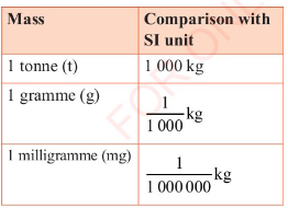
The SI unit of mass is the kilogramme, written as kg. Other
units of mass based on kilogramme are tonne (t), gramme (g) and
milligramme (mg). Their equivalences are as given below. See
also Table 3.6.
1 tonne = 1 000 kg.
1 kilogramme = 1 000 g.
1 gramme = 1 000 mg.
Mass should not be confused with weight as is evidenced in
day-to-day discussions and conversations. Weight is defined as a
measure of the gravitational force acting on an object, or is
the measure of how heavy an object is.
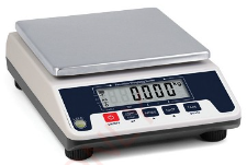
Measurement of mass using different instruments
The equipment commonly used to measure the mass of an objects in
the laboratory is digital (electronic) balance, shown in Figure
3.21 (a), or triple beam balance shown in Figure 3.21 (b).
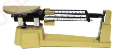
A triple beam balance
A triple beam balance shown in Figure 3.21 (b) is used to
measure the mass of an object. Its unit of measurement is the
gramme.
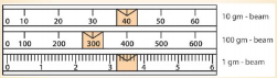
It is called triple beam balance because it contains three
beams, each with specified standard mass graduations or
markings.
The first beam has 100 g graduations, the second has 10 g
graduations while the third beam has 1 g graduations with 0.1 g
graduations in between. To measure the mass of an object, the
weights which are normally attached to each beam, are moved
along the beams.
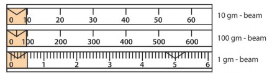
How to use a triple beam balance (Depends on the mass)
1. With the pan empty, move the three weights to the left of the
beams, so that the balance reads zero, as shown in Figure 3.22.
The balance pointer should be straight and aligned with the
fixed mark at the right of the balance. If the pointer is not
straight, use the counter weight to adjust as needed.
2. Once the balance has been adjusted, place the object to be
measured on the pan.
3. Move the 100-gram weight to the right along its beam until
the indicator just drops below the fixed mark. The mark to the
immediate left of this point indicates the number of hundreds of
grams. Note down this value which is 0 for the case of Figure
3.23.
4. Move the 10 gram weight to the right along its beam until the
indicator drops below the fixed mark. The mark immediately to
the left of this point indicates the number of tens of grams.
Note down this value, 20 for the case of Figure 3.23.
5. Move the 1 gram weight to the right along its beam until the
pointer coincides directly with the fixed mark on the right, as
shown in Figure 3.23. Note down this value which is 5 and given
to the nearest tenth of a gram.
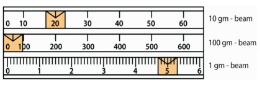
6. To find the mass of the object on the pan, add the numbers
from the three beams. That is, 0g + 20 g + 5 g = 25 g
Example 3.5
The diagram in Figure 3.24 shows the position of the three
weights on the beams of a triple beam balance. Determine the
mass of the object.
Solution
We start with 100 g, 10 g, then 1 g. That is, 300 g + 40 g + 3.5
g = 343.5 g.
A digital balance
A digital balance shown in Figure 3.21 (a) is a very sensitive
weighing balance. It can measure masses to an accuracy of one
thousandth of a gram (0.001 g).
The object whose mass is to be measured is placed on the pan on
top of the balance and the mass read from the digital display.
Task 3.6
In your regular discussion groups, carry out the following:
1. Use a triple beam balance to measure the mass of your physics
textbook, exercise book and your pen.
2. Use a digital balance to measure the mass of the same
materials.
3. Compare the two measurements and discuss any differences.
Exercise 3.3
Answer all questions
1. Differentiate between estimated length and measured length.
2. State three basic fundamental quantities of measurement and
their SI units.
3. Explain how the following fundamental physical quantities can
be measured:
(a) Length.
(b) Mass.
(c) Time.
4. Differentiate between the following items:
(a) A stopwatch from a stopclock.
(b) An analogue from a digital stopwatch.
(c) Mass from weight.

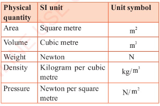
Derived quantities are obtained by combining the fundamental
quantities through the application of basic arithmetic
operations, namely multiplication and/or division. Their units
are called derived units and the same method is used in deriving
them. Examples of derived quantities are area, volume, density,
velocity and acceleration. Their derived units are m², m³,
kg/m³, m/s and m/s², respectively, as shown in Table 3.7.
These quantities are calculated using certain formulae or they
are determined experimentally. For example,
Area (4) of a square = length (1) × length (1) = 1 × 1 = P.
The SI unit of area is the square metre, m². However, areas of
other regular shapes are calculated using Student's Book Form
One their respective formulae depending on the shape of the
object. This will be learnt more in mathematics lessons, though
a few of them will be discussed in this textbook.
Measurement of volume
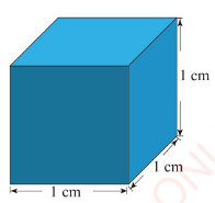
Volume is the quantity of space that an object occupies. The SI
unit of volume is cubic metre (m³). One cubic metre is the
volume of a cube with sides 1 m long. Other units of volume
includes:
(a) cubic centimetre (cm³);
(b) millilitre (ml); and
(c) litre (1).
The cubic metre is rather a large unit of volume for everyday
school laboratory work. For convenience purposes, volumes are
measured using the cubic centimetre (cm³). One cubic centimetre
is the volume of a cube with sides 1 cm long, as shown in Figure
3.25.
Techniques for measuring volume
The techniques for measuring volume do vary depending on whether
the sample is liquid, solid, or gas.
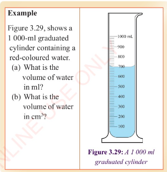
Liquids
Litre is another unit used for measuring the volume of liquids.
1 litre (1) = 1 000 cm³= 1 000 ml. This implies that 1 cm³ = 1
ml. The volume of water in a 1- litre = 1 / 1 000 m³ as shown in
Figure 3.26.

Several graduated apparatus such as a graduated cylinder,
burette or pipette are usually used to measure the volume of a
liquid in the laboratory. Calibrated beakers and flasks can also
be used. In rare cases, syringes are used for measuring the
volume of liquids. A burette, a pipette or a volumetric flask
gives accurate measurement of liquid volumes.
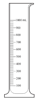
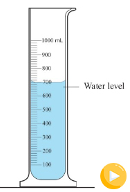
Measurement of volume using a measuring cylinder
Graduated measuring cylinders are used to measure the volume of
a liquid, ranging from a few millilitres to hundreds of
millilitres. They are of different sizes, made of glass or
plastic. Measuring cylinders are graduated from the bottom
upwards. They measure the volume of liquids that are poured into
them. An example of a measuring cylinder is shown in Figure
3.27.
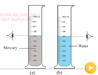
When reading a measuring cylinder, the cylinder must be placed
on a level surface.
The curve in the upper surface of the liquid is called the
meniscus. The meniscus can curve upward (concave) or downward
(convex) depending on the liquid and the material of the
cylinder. The volume of the liquid is read at the top of the
meniscus or at the bottom of the meniscus, as illustrated in
Figure 3.28 (a) and 3.28 (b), respectively. Note that the eye
level should be in line with the meniscus of the liquid.
Task 3.7
Carry out the following task in groups of four students. Fill a
drinking cup with water and then pour the water into a graduated
measuring cylinder.
Measure the volume of water and record. What is the reading on
the cylinder?
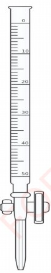
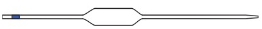
Measurement of volume using a burette
A burette is a vertical cylindrical piece of laboratory
glassware with a volumetric graduation on its full length and a
precision tap, or stopcock on the bottom, as shown in Figure
3.30. It is used to dispense a required amount of a liquid
reagent for which high precision is desired. A burette is
graduated from the top downwards and measures the volume of a
liquid that runs out from it.
The use of a burette involves the following steps:
1. Pour the liquid into the burette and make sure that it does
not pass the 0 mark at the top. Note down this volume, say V₁.
2. Note down the value of the amount of liquid you require to
use, say V and add it to V, to get V₂
3. Open the tap and let the liquid runs until the level of the
liquid reaches V₂.
4. Subtracting V, from V₂ gives V.
Measurement of volume using a pipette
A pipette is a glass or plastic tube, usually open on both ends.
A pipette is shown in Figure 3.31. It is used to transfer a
known amount of a liquid from one container to another. The
liquid is sucked into it until it reaches the level of the mark
shown.
Sometimes a flexible rubber bulb is placed at one end of the
pipette to aid in sucking the liquid from a container, as shown
in Figure 3.32.
Common laboratory pipettes are calibrated with 20 cm³, 25 cm³ or
50 cm³. The 20 cm³ pipette is used to measure 20 ml of liquid
while the 25 cm³ and 50 cm³ pipettes are used to measure 25 ml
and 50 ml of liquid, respectively. This shows that pipettes are
specifically made for transferring small amounts of liquids only
from one container to another.
Activity 3.4
Aim:
To measure volume of water using a pipette.
Materials:
Pipette, beaker, graduated cylinder, water
Procedure
1. Pour 100 ml of water into a beaker.
2. Transfer 25 ml of water from the beaker to a graduated
cylinder using a pipette.
3. Observe the meniscus of the water in the cylinder and record
its reading.
4. Record the volume of water in the graduated cylinder.
Do Activity 3.4
Questions
(a) Compare the original volume of water in the pipette with the
volume of water in the cylinder and state your observations.
(b) Is the volume of water transferred from the beaker equal to
reading in the cylinder? Explain.
(c) Discuss your findings.
The volume of water transferred into the measuring cylinder
equals the volume of the pipette. This is because the volume of
a liquid does not change, irrespective of the apparatus used.
Measurements of a volume of a solid
(a) Determining the volume of regular objects
Dimensions of a solid with regular shape such as a cube, a
cylinder or a sphere, can be measured and the appropriate
formula is used to calculate its volume.
For example;
Volume (V) of a rectangular block = length (I) height (h) x
width (w). For a cube, I = h = w,
Volume of a cylinder
= π × (radius,r)² × (height, h) = πr² h
Volume of sphere = 4 / 3 πr²
Example 3.6
Calculate the volume of a rectangular block, of sides 15 cm, 8
cm and 7 cm, as shown in Figure 3.33.
Solution
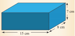
Volume of the block = l × w x h
= 15 cm x 8 cm x 7 cm = 840 cm³.
Example 3.7
Calculate the volume of the cylinder shown in Figure 3.34, given
that π = 3.14.
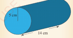
Solution
Given, π = 3.14, r = 5 cm and 1 = 14 cm Formula for calculating
volume of a cylinder V = πr²l
Substituting in the formula gives,
V=3.14 x 5 cm x 5 cm x 14 cm = 1099 cm³.
(a) Determining the volume of irregular solid objects
Measuring the volume of an irregular shaped solid object is
based on the Archimedes' principle which states that 'when an
object is completely submerged in water, it displaces a volume
of water equal to its own volume'. The displacement or immersion
method is used.
The volume of an irregular object can be measured using:
(a) a measuring cylinder; and
(b) eureka can or an overflow can.
Volume of irregular object by using a graduated cylinder
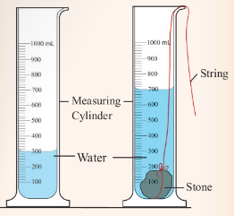
Suppose you want to measure the volume of a small stone.
The following steps are necessary.
1. Fill a graduated cylinder with about 300 ml of water as shown
in Figure 3.35 (a).
2. Carefully measure the initial volume of water V₁.
3. Then gently lower the stone into the water as shown in Figure
3.35 (b).
4. Read the final volume of water V₂.
5. The difference between the final and the initial volume gives
the volume of the stone.
Volume of the stone (V
s
)
final volume (V₂) - initial volume (V₁)
V
s
= V₂ - V₁.
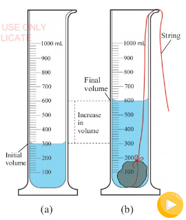
In the illustration,
V
s
= 600 ml - 300 ml = 300 ml.
Example 3.8
When an irregular solid object was immersed in 65 cm³ of water,
the water level rose to 81 cm³. What was the volume of the
irregular solid object?
Solution
Initial volume of water V₁ = 65 cm³
Final volume of water V₂ = 81 cm³
Using volume of solid, V = V₂ - V₁
gives
V
s
= 81 cm³ - 65 cm³ = 16 cm³
Therefore, the volume of the irregular solid is 16 cm³.
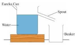
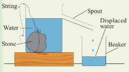
Volume of an irregular objects by using eureka can
If the object is too large to fit into the graduated cylinder,
an alternative method is to use an overflow can commonly known
as a eureka can as shown in Figure 3.36.
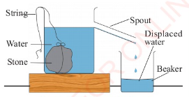
This is a large can with an overflow spout near the top. In
practice, the following steps are involved when using an
overflow can to measure the volume of an irregular object.
1. Fill the eureka can with water up to the level of the spout.
2. Tie the irregular object with a string.
3. Gently lower the object into the water using the string.
4. The object will displace some water which will be collected
in the beaker, as shown in Figure 3.37.
5. Transfer the displaced water into a graduated cylinder, as
shown in Figure 3.38.
6. Measure the volume of the displaced water which is equal to
the volume of the object.
Note: Hence, the volume of solid objects with irregular shape
can be determined by using immersion methods.
Activity 3.5
Aim:
To measure volume of an irregular object using a eureka can.
Materials:
eureka can, stone, water, beaker, graduated cylinder, string
Procedure
1. Set up the apparatus as in Figure 3.39.
2. Tie the stone with a string and gently lower it into the
water contained in the eureka can.
3. Collect the overflowing water in the beaker below the spout.
4. Measure and record the volume of the displaced water using a
measuring cylinder.
5. This volume is equal to the volume of the stone.
Do Activity 3.5
Questions
(a) Why must the stone be tied and gently lowered into the
water?
(b) Why is the water in the eurica can displaced when the stone
is immersed?
The stone is tied before lowering it so as to prevent water from
splashing. This would give wrong results as the remaining water
level would be lower than the spout level.
It would also interfere with the volume to be measured. The
water is displaced so as to give room for the stone. The stone
occupies a volume which is equal to the volume of water
displaced.
If the solid has an irregular shape such as a stone, it is
submerged in a measuring cylinder containing water and the
volume of water displaced is taken as the volume of the solid.
Determination of volume of gases
A gas always fills any container into which it is placed.
Therefore, the volume of a gas can be determined by measuring
the Student's Book Form One volume of the container into which
it is put. The volume of the container can be determined from
its dimensions or by filling it with water and then pouring the
water into a graduated cylinder.
Exercise 3.4
Answer all questions
1. Calculate the volume of a cube of sides 2 cm.
2. The volume of a brick is given as 60 cm³. Given that its
length and width are 6 cm and 4 cm respectively, calculate its
height.
3. A cylindrical container has a diameter of 10 cm and a height
of 12 cm. Calculate its volume, given that π = 3.14.
4. A beaker contains 100 cm³ of liquid. A 25 cm³ pipette is used
twice to transfer the liquid to another beaker. What is the
volume of the liquid left in the original beaker?
5. The initial volume in a burette was read as 80 cm³. X cm³ of
the liquid was run out and the final volume was read as 57 cm³.
Calculate the value of X.
6. What is the volume of an irregular solid immersed in 50 cm³
of water contained in a beaker if it raises the water level to
57 cm³.
While taking any measurement, there may be some error in the
reading. An error is defined as a deviation from the actual
reading. However, there is a more precise definition. An error
is a measure of estimated difference between the measured value
and the actual value of a physical quantity that is being
measured or observed. Errors usually arise due to several
reasons:
1. Fault during manufacture - If a measuring instrument is not
manufactured as per specification, then the accuracy is lowered.
2. Damage during use - Bad handling of instruments can lead to
incorrect results. Each apparatus should be used properly and
for the right purpose.
3. Poor storage-Apparatus should be well stored away from
factors that affect their accuracy like dust and heat.
4. Human factors - Errors can arise when an experimenter does
not take readings from an instrument properly. The three common
errors due to improper reading of an instrument are:
(i) Parallax error;
(ii) Zero error; and
(iii) Instrumental error.
Parallax error
Parallax error occurs when an observer takes measurement from
wrong positions. Consider Figure 3.40.
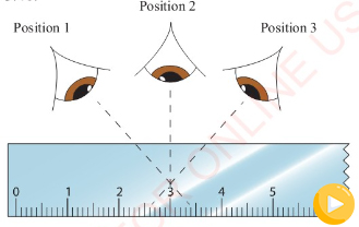
Positions 1 and 3 will give higher and lower readings than
position 2. A reading taken at position 2 will be correct
because the observer has positioned his/her eyes directly above
the mark to be read. To minimize parallax error, the observer
must position his/her eyes directly above the mark to be read.
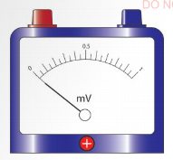
Zero error
For a measurement to be considered accurate, the initial reading
of a pointer should be at a zero mark.
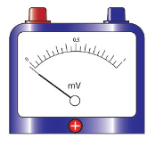
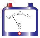
When a measurement is taken with an instrument with the pointer
below or above the zero mark as shown in Figure 3.41 (a) and
Figure 3.41 (b), zero error is said to occur.
To minimise zero error, the instrument should be adjusted to
read zero, as shown in Figure 3.42. A pointer can be adjusted to
read zero.
For example, in a vernier caliper, zero error arises when the
zero mark on the main and vernier scales do not coincide with
each other when the jaws are closed. A micrometer screw gauge
may also have zero error if the zero marks on the spindle and
sleeve do not coincide after closing the gap between the spindle
and the anvil.
Instrumental error
An instrumental error is caused by an instrument itself. The
error occurs because of defects in the instrument used in taking
a measurement. These defects can be from the manufacturer or
they may result from poor handling of the instrument. Sometimes
errors of this type may occur when the instrument used for
measuring is overheated. Also, insensitivity of the instrument
can result in this error. To minimise these errors, avoid
overheating instruments, maintain them regularly and store all
instruments in a safe place free from dust. Proper handling of
instruments is also recommended.
Chapter summary
1. Initially, approximations were used as a form of measurement.
Advancement in science has made it possible to have appropriate
instruments for each type of measurement.
2. Every measurement has the number part and the unit part. This
complete measurement is called measurement of a physical
quantity.
3. Fundamental quantities are the physical quantities which
cannot be . obtained from any other quantities. These quantities
include length, mass, time, temperature, amount of substance,
electric current and luminous intensity.
4. The three fundamental quantities of measurement are mass,
length and time. Their SI units are the kilogramme, metre and
second, respectively.
5. The beam balance and digital balances are used to measure
mass, while rulers, vernier calipers, micrometer screw gauges
and tapes are used to measure length. On the other hand, time is
measured using a stopwatch or a clock.
6. Derived quantities are obtained by dividing or multiplying
two or more fundamental quantities. These quantities include
weight, acceleration, velocity, volume and area. Their SI units
are the Newton, metre per second square, metre per second, cubic
metre, and square metre, respectively.
7. There are three types of errors that emerge during
measurements, namely:
(a) parallax error;
(b) zero error; and
(c) instrumental error.
Revision exercise 3
Section A
Choose the most correct answer
1. To measure the length using a metre rule, wrong position of
the eye leads to:
(a) parallax error.
(b) eye error.
(c) zero error.
(d) metre error.
2. Which of the following instruments is most suitable for
measuring the internal diameter of 100 ml beaker?
(a) Metre rule.
(b) Vernier caliper.
(c) Measuring tape.
(d) External caliper.
3. The mass of an object is reduced if its
(a) state is changed.
(b) amount of matter is reduced.
(c) surface is reduced.
(d) volume is reduced.
4. A cuboid with length 3 cm, width 4 cm and height 10 cm is
made from wood. The actual volume of the cuboid is
(a) 120 cm³.
(b) 240 ml.
(c) 120 m³.
(d) 240 cm³.
5. What is the zero error shown in the Figure 3.43?
(a) 0.3 mm.
(b) 0.7 mm.
(c) -0.3 mm.
(d) -0.7 mm.
Section B
6. (a) From the list given below classify them in terms of
regular or irregular shape.
cube, orange, stone, banana, water pipe, a house, cuboid,
chalkboard.
(b) The internal and external radius of a hollow silver sphere
are 7 cm and 14 cm, respectively. Find its volume.
7. (a) Write down the principal steps used in reading the
vernier caliper.
(b) In a vernier calliper, there are 10 divisions on the vernier
scale and 1 cm on main scale is divided in 10 parts. While
measuring a length, the zero of the vernier scale lies just
ahead of 1.8 cm mark and 4th division of vernier scale coincides
with a main scale division. Find the value of the length.
8. (a) Differentiate between the mass and the volume of a
substance.
(b) Figure 3.44 shows a measuring cylinder containing water
before and after a stone is immersed. What is the volume of the
stone?
9. (a) Figure 3.45 shows a metre rule being used to measure the
length of a textbook.
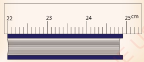
What is the approximate length of the book?
(b) Explain why it is advised to start at the mark beyond 1 cm
when taking a measurement using a metre rule.
10. A physics student obtained the following results for the
diameter of the same wire from an experiment: 0.35 mm, 0.36 mm
and 0.34 mm. Calculate the diameter of the wire.
11. A rectangular block measures height 1.00 cm, width 2.50 cm,
and length 4.00 cm.
(a) What instrument was used to measure the sides of the
rectangular block?
(b) Calculate the volume of the rectangular block.